


Detailed Technical Points for Basalt Fiber Continuously Reinforced Composite Pavement Construction
I. Preprocessing and Positioning of Composite Reinforcement Rolls
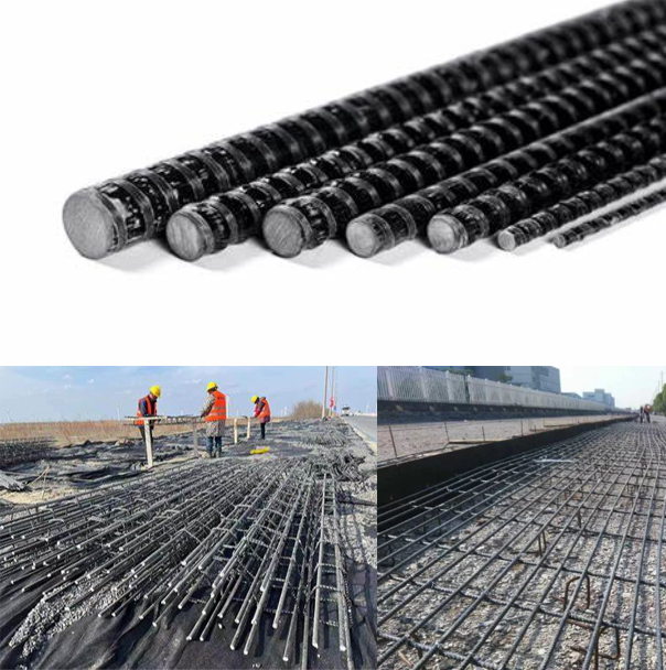
1. Storage and Unpacking of Reinforcement Rolls
- Specifications: Each roll of basalt fiber composite reinforcement measures 600 m in length and weighs 18 kg.
- Handling: Store rolls horizontally in circular frames. Remove the outer packaging and carefully guide the reinforcement end to the designated position to avoid twisting or bending.
2. Baseline Surveying
- Use a total station or laser alignment equipment to precisely mark the layout positions of the composite reinforcement mesh and joint locations based on design drawings. Critical control points must be clearly identified.
II. Installation and Binding of Composite Reinforcement Mesh
1. Transverse Reinforcement Installation
- Install transverse reinforcements on support seats, ensuring a 60° angle with longitudinal reinforcements. Securely bind the ends to prevent displacement.
- Height Control: The composite reinforcement mesh should be 10 cm lower than the pavement panel, with the outer reinforcement center kept ≥90 mm from free edges.
2. Support Structure Construction
- Fabricate U-shaped steel supports using Φ25 mm ribbed Steel Bars, spaced 25 cm longitudinally and 50 cm transversely, to stabilize the composite reinforcement mesh.
- Place main load-bearing composite reinforcements in areas of maximum bending stress, with transverse reinforcements spaced 50 cm at the bottom of longitudinal bars.
3. Protective and Wear-Resistant Layers
- Bottom Protective Layer: A 180 mm thick protective layer is set between the reinforcement mesh and subbase to prevent erosion.
- Top Wear-Resistant Layer: A 50 mm thick wear-resistant layer is installed atop the mesh to enhance pavement durability.
III. Longitudinal Reinforcement and Joint Construction Control
1. Longitudinal Reinforcement Spacing and Precision
- Longitudinal reinforcement spacing must be ≤250 mm and exceed 2.5 times the peak aggregate size (e.g., for a 10 mm aggregate peak, spacing ≥25 mm).
- Use positioning clamps to ensure installation accuracy, with deviations controlled within ±5 mm.
2. Longitudinal Joint Tie Bars
- Φ25 mm ribbed steel bars are used for longitudinal joint tie bars, densely arranged in joint areas.
- Full-width paving sections may omit longitudinal joints to eliminate structural weak points.
IV. Prestressed Reinforcement and Support Installation
1. Prestressed Longitudinal Composite Reinforcement
- Use Φ25 mm steel bars as prestressed longitudinal reinforcements, with anchorage lengths strictly controlled at 3.0 m.
- Overlap lengths range 60–100 cm, secured with epoxy resin after binding to ensure seamless connections.
2. Support Prefabrication and Fixation
- Prefabricate steel supports and lap joints as per design. Drill holes **10–15 cm from free edges and longitudinal joints** in the subbase, embed supports, and weld anchor bars.
V. Construction Standards and Quality Control
1. Regulatory Compliance
- Strictly adhere to GB 50010—2010 (Code for Design of Concrete Structures) for overlap binding, protective layer thickness, and other parameters.
2. Key Acceptance Criteria
- Flatness deviation of the reinforcement mesh: ≤3 mm/m.
- Perform pull-out tests on epoxy resin-bonded areas, requiring a bond strength of ≥2.5 MPa.
VI. Common Issues and Solutions
- Issue 1: Mesh Misalignment
Solution: Install temporary clamps and positioning frames at 5 m intervals.
- Issue 2: Weak Epoxy Bonding
Solution: Ensure bonding surfaces are clean and dry. Control curing temperature at 15–30°C and curing time ≥24 hours.
VII. Construction Flowchart
Reinforcement Roll Positioning → Baseline Surveying → Transverse Reinforcement Installation → Support Structure Assembly → Longitudinal/Transverse Reinforcement Layout
↓
Protective/Wear-Resistant Layer Installation → Longitudinal Joint Tie Bar Dense Arrangement → Prestressed Reinforcement Anchoring → Epoxy Resin Bonding
↓
Quality Inspection → Proceed to Next Phase